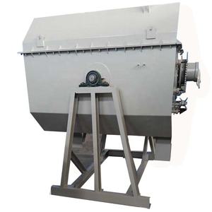
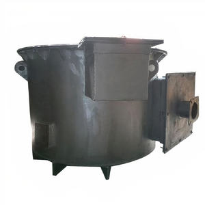
Drawing heavy machinery is a critical task that requires a combination of technical expertise, precision, and adherence to industry standards. As a mechanical engineer, creating accurate and functional drawings ensures that machinery components are manufactured, assembled, and maintained correctly. Below is a structured approach to drafting heavy machinery, covering essential steps, tools, and best practices.
(how to draw a heavy machinery)
**1. Understand Design Requirements and Specifications**
Begin by gathering all technical specifications, functional requirements, and operational constraints. Review client or project documentation to identify load capacities, material strengths, environmental conditions, and safety regulations. Collaborate with stakeholders—such as design teams, manufacturers, and end-users—to align expectations. This phase sets the foundation for the entire design process.
**2. Develop Preliminary Sketches**
Start with freehand sketches or 2D CAD (Computer-Aided Design) drafts to visualize the machinery’s layout. Focus on defining the overall structure, component placement, and motion mechanisms. Prioritize ergonomics, accessibility for maintenance, and spatial relationships between subsystems. These sketches serve as a blueprint for detailed modeling and help identify potential design conflicts early.
**3. Create 3D Models Using CAD Software**
Transition to 3D CAD tools like AutoCAD, SolidWorks, or CATIA to build a digital prototype. Model each component with precise dimensions, ensuring alignment with mechanical and geometric tolerances. Pay attention to critical elements such as gears, hydraulics, and structural supports. Use parametric modeling to maintain design flexibility, allowing easy adjustments as requirements evolve. Validate interference checks to prevent part collisions during operation.
**4. Detail Engineering Drawings**
Generate orthographic projections (front, top, side views) and sectional views to illustrate internal features. Include exploded views to clarify assembly sequences. Annotate drawings with dimensions, surface finishes, welding symbols, and material specifications (e.g., ASTM grades). Specify tolerances for machined parts to ensure interchangeability. Use standardized drawing templates compliant with ISO or ASME Y14.5 guidelines to maintain consistency.
**5. Incorporate Mechanical Systems and Dynamics**
Integrate mechanical systems such as power transmission, hydraulic circuits, or pneumatic systems into the design. Simulate motion using software like MATLAB or ANSYS to evaluate stress distribution, vibration, and fatigue. Optimize components like bearings, shafts, and fasteners based on load analysis. Ensure compatibility with auxiliary systems (e.g., electrical controls) by coordinating with multidisciplinary teams.
**6. Validate Through Finite Element Analysis (FEA)**
Perform FEA to assess structural integrity under operational loads. Identify stress concentrations, deformation risks, or failure points in critical parts like booms, frames, or joints. Iterate the design to reinforce weak areas, possibly by adjusting thicknesses, adding ribs, or selecting higher-grade materials. Validate thermal and fluid dynamics if the machinery involves heat exchangers or hydraulic systems.
**7. Prepare Manufacturing and Assembly Documentation**
Produce detailed Bill of Materials (BOM) listing part numbers, quantities, and raw materials. Provide machining instructions, including tolerances, surface treatments, and heat treatment processes. For welded or bolted assemblies, specify weld types, bolt grades, and torque values. Include assembly drawings with step-by-step guidelines to streamline production and reduce errors.
**8. Review and Compliance Checks**
Conduct a design review with cross-functional teams to verify compliance with safety standards (e.g., OSHA, ISO 12100). Ensure drawings meet industry-specific regulations, such as ISO 286 for fits and tolerances or DIN standards for European markets. Address feedback and revise drawings iteratively before final approval.
**9. Leverage Collaboration Tools**
Use Product Data Management (PDM) systems to manage drawing revisions and maintain version control. Share files via platforms like Autodesk Vault or Teamcenter to facilitate real-time collaboration. Ensure all stakeholders access the latest revisions to avoid discrepancies during manufacturing.
**10. Continuous Improvement**
Post-manufacturing, analyze field performance data to identify design improvements. Update drawings to reflect retrofits or component upgrades, maintaining an accurate as-built record.
(how to draw a heavy machinery)
In conclusion, drawing heavy machinery demands meticulous planning, advanced CAD proficiency, and a systematic validation process. By adhering to standardized practices and leveraging simulation tools, mechanical engineers can deliver robust, efficient designs that meet operational and safety objectives.


